TM 9-2320-365-20-3
b. Installation.
CAUTION
Ensure dipswitch settings are correct. Failure
to
comply
may
result
in
inaccurate
speedometer readings.
NOTE
Perform
steps
(1)
through
(3)
on
speedometer.
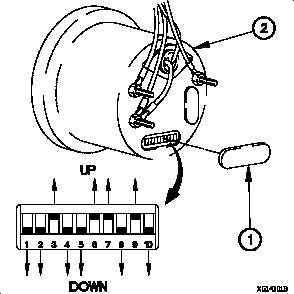
(1) Remove cover (1) from speedometer (2).
(2) Set dipswitches 3,6,7, and 9 in the up position.
(3) Set dipswitches 1,2,4,5,8, and 10 in the down position.
NOTE
Note position of speedometer prior to
installation.
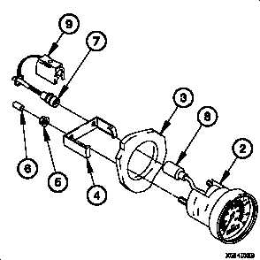
(4) Position speedometer (2) in instrument panel assembly
(3) with retaining ring (4) and two self-locking nuts (5).
(5) Tighten two self-locking nuts (5) to 9 lb-in. (1 N·m).
(6) Install two protective caps (6) on speedometer (2).
NOTE
Install plastic cable ties as required.
(7) Connect connector PX8 (7) on speedometer connector
(8).
(8) Connect connector clamp (9) on speedometer connector
(8).
c. Follow-On Maintenance.
(1) Install instrument panel assembly (para 7-15).
(2) Check gage(s) operation (TM 9-2320-365-10).
End of Task.
Change 1
7-87