TM 9-2320-365-20-3
7-16. LIGHTED INDICATOR DISPLAY REPLACEMENT/REPAIR
This task covers:
a. Removal
b. Disassembly
c. Assembly
d. Installation
e. Follow-On Maintenance
INITIAL SETUP
Equipment Conditions
Batteries disconnected (para 7-48).
Tools and Special Tools
Tool Kit, Genl Mech (Item 44, Appendix C)
Wrench, Torque, 0-75 lb-in. (Item 86, Appendix B)
Materials/Parts
Lamp, Incandescent (Item 57, Appendix G)
Lamp, Incandescent (Item 58, Appendix G)
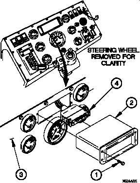
a. Removal.
(1) Remove four screws (1) and lighted indicator display (2)
from instrument panel assembly (3).
(2) Disconnect connector PX7 (4) from lighted indicator
display (2).
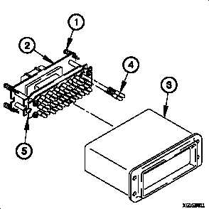
b. Disassembly.
(1) Loosen four captive screws (1) in lamp mounting panel
(2).
(2) Remove lamp mounting panel (2) from lighted indicator
display housing (3).
(3) Remove faulty lamp(s) (4) from printed circuit board (5).
Discard faulty lamp(s).
7-105