TM 9-2320-365-20-1
2-443
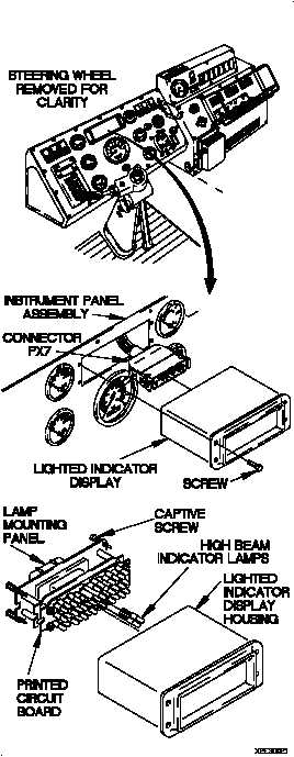
CONTINUITY TEST
(1) Loosen four captive screws in lamp mounting
panel.
(2) Remove lamp mounting panel from lighted
indicator display housing.
(3) Remove high beam indicator lamps from
printed circuit board.
(4) Set multimeter to ohms.
(5) Check continuity through each high beam
indicator lamp and note reading on
multimeter.
(6) If continuity is not present, replace lamps
(para 7-16).
(7) If continuity is present, replace lighted
indicator display (para 7-16).
(8) Install high beam indicator lamps in
printed circuit board.
(9) Install lamp mounting panel in lighted
indicator display housing.
(10) Tighten four captive screws in lamp
mounting panel.
(11) Connect lighted indicator display to connector
PX7.
(12) Position lighted indicator display in instrument
panel assembly with four screws.
(13) Tighten four screws to 6-10 lb-in. (1 N·m).
(14) Connect batteries (para 7-48).