VOLTAGE TEST
NOTE
Inspect connector pins/sockets for damage,
corrosion, and serviceability. Check that
connector pins are not pushed back or not
capable of making good contact.
Use care when testing electrical connectors.
Do not damage connector pins or sockets
with multimeter probes. Failure to comply
may result in damage to equipment.
CAUTION
WARNING
Remove rings, bracelets, watches, necklaces,
and any other jewelry before working around
vehicle. Jewelry can catch on equipment and
cause injury or short across electrical circuits
and cause severe burns or electrical shock.
Change 1 2-502.1
TM 9-2320-365-20-1
(1) Set multimeter to volts DC.
(2) Connect positive (+) probe of multimeter
to connector PX7 pin 27.
(3) Connect negative (-) probe of multimeter to
ground.
(4) Connect batteries (para 7-48).
(5) Position master power switch to on
(TM 9-2320-365-10) and note reading on
multimeter.
(6) Position master power switch to off
(TM 9-2320-365-10).
(7) Disconnect batteries (para 7-48).
(8) If 24 VDC is not present, repair wire 1658
from connector PX7 pin 27 to terminal
board TB1 position 61 (para 2-40) or
replace WTEC II dashboard cable
assembly (para 7-10) or WTEC III
dashboard cable assembly (para 7-11).
(9) If continuity is present, replace rear air
pressure transmitter (para 7-36).
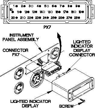
(10) Connect lighted indicator display connector
to connector PX7.
(11) Position lighted indicator display in
instrument panel assembly with four
screws.
(12) Tighten four screws to 6-10 lb-in. (1 N·m).
(13) Connect batteries (para 7-48).