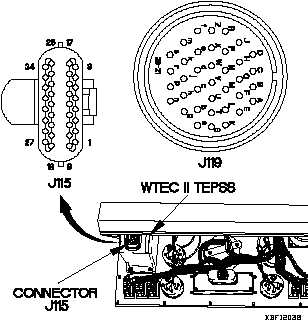
(10) Connect negative (-) probe of multimeter to
connector J119Z and note reading on
multimeter.
(11) If continuity is not present from connector
J115-1 to connector J119a and J119Z,
replace WTEC II cab transmission harness
(para 7-86).
(12) If continuity is present, replace WTEC II TEPSS
(para 8-2).
(13) Install instrument panel assembly (para 7-15).
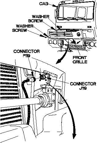
(14) Connect connector P119 to connector J119.
(15) Position front grille on cab with washer and
screw.
(16) Position two washers and screws in front
grille.
(17) Tighten screw to 48-60 lb-in. (5-7 N·m).
(18) Tighten two screws to 24 lb-in. (3 N·m).
(19) Clear diagnostic codes (para 8-4).
(1) Remove two screws and washers from
front grille.
(2) Remove screw and washer from front
grille.
(3) Remove front grille from cab.
(4) Disconnect connector P119 from
connector J119.
(5) Remove instrument panel assembly for
access (para 7-15).
(6) Disconnect connector J115 (top
connector) from WTEC II TEPSS.
(7) Set multimeter to ohms.
(8) Connect positive (+) probe of multimeter
to connector J115-1.
(9) Connect negative (-) probe of multimeter
to connector J119a and note reading on
multimeter.
CONTINUITY TEST
TM 9-2320-365-20-2
Change 1 2-1435