CAUTION
Use care when testing electrical connectors.
Do not damage connector pins or sockets
with multimeter probes. Failure to comply
may result in damage to equipment.
NOTE
Inspect connector pins/sockets for damage,
corrosion, and serviceability. Check that
connector pins are not pushed back and
are capable of making good contact.
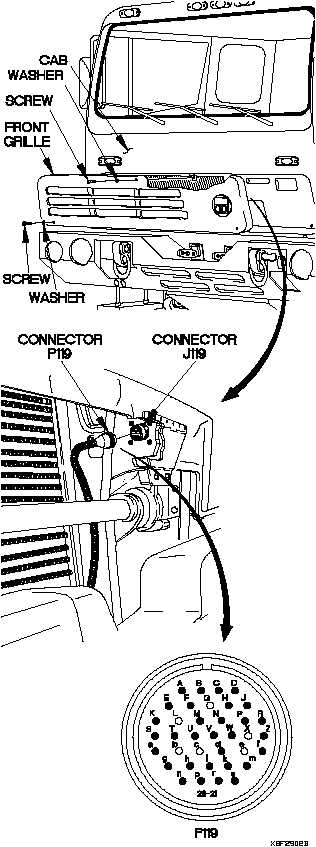
RESISTANCE TEST
(1) Remove two screws and washers from
front grille.
(2) Remove screw and washer from front
grille.
(3) Remove front grille from cab.
(4) Disconnect connector P119 from
connector J119.
(5) Set multimeter to ohms.
(6) Connect positive (+) probe of multimeter
on P119h.
(7) Connect negative (-) probe of multimeter
on P119j and note reading on multimeter.
(8) If 2 ohms (or less) resistance is present,
notify DS Maintenance.
(9) If resistance is greater than 2 ohms,
replace WTEC III transmission ECU
(para 8-7).
(10) Connect connector P119 to connector
J119.
(11) Position front grille on cab with washer
and screw.
(12) Position two washers and screws in front
grille.
(13) Tighten screw to 48-60 lb-in. (5-7 N·m).
(14) Tighten two screws to 24 lb-in. (3 N·m).
(15) Clear diagnostic codes (para 8-5).
TM 9-2320-365-20-2
Change 1 2-1535