TM 9-2320-365-20-4
16-54. M1079 FAN SWITCH/BOX AND CONDUIT REPLACEMENT
This task covers:
a. Removal
b. Installation
c. Follow-On Maintenance
INITIAL SETUP
Equipment Conditions
Engine shut down (TM 9-2320-365-10).
AC power disconnected (TM 9-2320-365-10).
Batteries disconnected (para 7-48).
LH and RH doors opened (115 degrees) (TM 9-
2320-365-10).
Tools and Special Tools
Tool Kit, Auto Fuel and Electrical System Repair
(Item 42, Appendix C)
Tools and Special Tools (Cont)
Tool Kit, Genl Mech (Item 44, Appendix C)
Heater, Gun Type, Electric (Item 20, Appendix B)
Materials/Parts
Dispenser, Pressure Sensitive Adhesive Tape (Item
21, Appendix D)
Splice, Conductor (Item 261, Appendix G)
Lockwasher (16) (Item 76, Appendix G)
a. Removal.
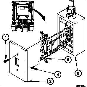
(1) Remove two screws (1) and cover (2) from outlet box
(3).
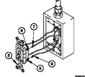
(2) Remove two screws (4) and switch S35 (5) from outlet
box (3).
NOTE
Tag wires and connection points prior to
disconnecting.
(3) Loosen screw (6) on switch S35 (5).
(4) Remove wire 415 terminal lug (7) from switch S35 (5).
(5) Loosen screw (8) on switch S35 (5).
(6) Remove wire 415A terminal lug (9) from switch S35 (5).
16-349


