CAUTION
Use care when testing electrical connectors.
Do not damage connector pins or sockets
with multimeter probes. Failure to comply
may result in damage to equipment.
(1) Set multimeter to ohms.
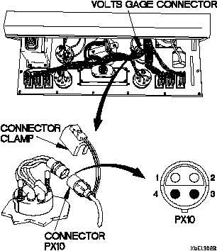
(2) Connect positive (+) probe of multimeter to
connector PX10 socket 1.
(3) Connect negative (-) probe of multimeter to
ground and note reading on multimeter.
(4) If continuity is not present, repair wire 3004
from connector PX10 socket 1 to terminal
board TB2 position 9 (para 2-40) or replace
WTEC II dashboard cable assembly (para
7-10) or WTEC III dashboard cable assembly
para 7-11).
(5) If continuity is present, replace VOLTS gage
(para 7-14).
(6) Connect connector PX10 to VOLTS gage
connector.
(7) Connect connector clamp on VOLTS gage
connector.
(8) Install instrument panel assembly (para
7-15).
CONTINUITY TEST
Inspect connector pins/sockets for damage,
corrosion, and serviceability. Check that
connector pins are not pushed back and
are capable of making good contact.
NOTE
Change 1 2-346.3
TM 9-2320-365-20-1