(1) Remove kick panel (para 16-3).
(2) Set multimeter to volts dc.
(3) Start engine (TM 9-2320-365-10).
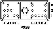
(4) Connect positive (+) probe of multimeter to
connector PX33-J1.
(5) Connect negative (-) probe of multimeter to
ground and note reading on multimeter.
(6) Connect positive (+) probe of multimeter to
connector PX33-J2.
(7) Connect negative (-) probe of multimeter to
ground and note reading on multimeter.
(8) If 12 to 14.5 vdc is not verified, repair wire
1900 (para 2-40) or replace WTEC II
dashboard cable assembly (para 7-10).
(9) Shut down engine (TM 9-2320-365-10).
VOLTAGE TEST
CAUTION
NOTE
Remove rings, bracelets, watches, necklaces,
and any other jewelry before working around
vehicle. Jewelry can catch on equipment and
cause injury or short across electrical circuit and
cause severe burns or electrical shock.
WARNING
Change 1 2-1475
Loose or dirty connectors may cause
intermittent loss of power to transmission
ECU and diagnostic codes to be logged.
Ensure that all connectors are clean and tight
before performing troubleshooting. Failure to
comply may result in incorrect test results.
Use care when testing electrical connectors.
Do not damage connector pins or sockets
with multimeter probes. Failure to comply
may result in damage to equipment.
Inspect connector pins/sockets for damage,
corrosion, and serviceability. Check that
connector pins are not pushed back and
are capable of making good contact.
TM 9-2320-365-20-2