TM 9-2320-365-20-3
4-17. HAND THROTTLE LEVER REPLACEMENT/ADJUSTMENT
This task covers:
a. Removal
b. Installation/Adjustment
c. Follow-On Maintenance
INITIAL SETUP
Equipment Conditions
Instrument panel assembly removed for access
(para 7-15).
Tools and Special Tools
Tool Kit, Genl Mech (Item 44, Appendix C)
Scale, Weighing (Item 30, Appendix C)
Materials/Parts
Washer, Spring (Item 281, Appendix G)
a. Removal.
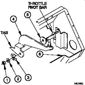
Remove nut (1), washer (2), spring washer (3), HAND
THROTTLE lever (4), and friction disk (5) from dashboard
(6). Discard spring washer.
b. Installation/Adjustment.
WARNING
Tab of HAND THROTTLE lever must be
positioned above throttle pivot bar.
Failure to comply may result in injury to
personnel or damage to equipment.
(1) Position friction disk (5), HAND THROTTLE lever (4),
spring washer (3), washer (2), and nut (1) on dashboard
(6).
CAUTION
HAND THROTTLE lever nut must be
tightened so that 9-11 lbs (40-49 N) of force
is required to change position of HAND
THROTTLE lever. Failure to comply may
result in damage to equipment.
(2) Tighten nut (1) on HAND THROTTLE lever (4).
4-87


