TM 9-2320-365-20-3
7-8. AUXILIARY PANEL REPLACEMENT
This task covers:
a. Removal
b. Installation
c. Follow-On Maintenance
INITIAL SETUP
Equipment Conditions
Batteries disconnected (para 7-48).
Tools and Special Tools
Tool Kit, Genl Mech (Item 44, Appendix C)
Wrench, Torque, 0-75 lb-in. (Item 86, Appendix B)
Wrench, Torque, 0-200 lb-in. (Item 58, Appendix C)
Socket Set, Socket Wrench (Item 34, Appendix C)
Materials/Parts
Dispenser, Pressure Sensitive Adhesive Tape
(Item 21, Appendix D)
Decal (Item 9, Appendix G)
Nut, Self-Locking (2) (Item 145, Appendix G)
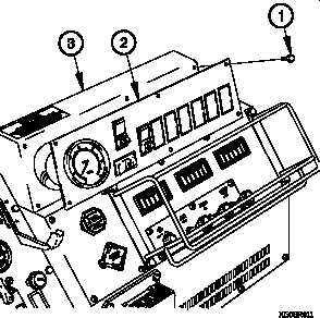
a. Removal.
(1) Remove six screws (1) from auxiliary panel (2).
(2) Lift auxiliary panel (2) outward from auxiliary panel
housing (3) to gain access.
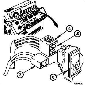
NOTE
• Tag electrical connectors and connection points
prior to removal.
• All rocker switches are removed the same way.
PTO switch shown.
(3) Lift tab (4) on connector P904 (5).
(4) Disconnect connector P904 (5) from PTO switch (6).
(5) Disconnect connector P904A (7) from PTO switch (6).
7-32