TM 9-2320-365-20-3
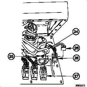
(12) Connect
vacuum
hose
(24)
to
AIR
FILTER
RESTRICTION GAUGE (25).
NOTE
• Vehicle serial numbers 0002 through 0017, 0019
through 0025, 0027 through 0031, 0033 through
0038, 0040 and 0041, 0043 through 0053, 0055
through 0089, 0091 through 0254, 0256 through
0258, 0260, 0261, 0263 through 2400, and 2402
through 3091 are not equipped with LAMP
TEST switch.
• Vehicle serial numbers 0001 through 1477 were
originally equipped with dashboard cable
assemblies containing two unused connectors
for LAMP TEST switch. Vehicle serial numbers
1478 through 3091 were originally equipped with
dashboard cable assemblies without connectors
for LAMP TEST switch.
• All rocker switches are connected the same
way. Hazard lights switch shown. Refer to
Table 7-2. Rocker Switch Connectors for
correct combinations of rocker switches and
connectors.
(13) Connect connector (26) to hazard lights switch (27).
(14) Connect connector (28) to hazard lights switch (27).
(15) Perform steps (13) and (14) on remaining rocker
switches.
NOTE
All electrical gages are connected the same
way. OIL PRESS gage shown. Refer to
Table 7-1.2 Electrical Gages Connectors
for correct combinations of gages and
connectors.
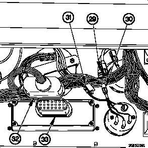
(16) Connect connector (29) to OIL PRESS gage connector
(30).
(17) Install connector clamp (31) on OIL PRESS gage
connector (30).
(18) Perform steps (16) and (17) on remaining electrical
gages.
(19) Connect connector PX7 (32) to lighted indicator display
(33).
Change 1
7-103


