TM 9-2320-365-20-3
10-3. DIFFERENTIAL SPIDER ASSEMBLY REPLACEMENT
This task covers:
a. Removal
b. Cleaning/Inspection
c. Installation
d. Follow-On Maintenance
INITIAL SETUP
Equipment Conditions
Engine shut down (TM 9-2320-365-10).
Tools and Special Tools
Tool Kit, Genl Mech (Item 44, Appendix C)
Wrench, Torque, 0-175 lb-ft (Item 57, Appendix C)
Goggles, Industrial (Item 15, Appendix C)
Gloves, Rubber (Item 13, Appendix C)
Pan, Drain (Item 24, Appendix C)
Materials/Parts
Rag, Wiping (Item 51, Appendix D)
Sealing Compound (Item 62, Appendix D)
Solvent, Dry Cleaning (Item 71, Appendix D)
Grease, Automotive and Artillery (GAA) (Item
23, Appendix D)
Packing, Preformed (4) (Item 185, Appendix G)
a. Removal.
NOTE
Front and rear axle differential spider
assemblies are removed the same way. Left
front axle differential spider assembly shown.
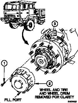
(1) Position fill port at 6 o’clock location.
(2) Drain oil from wheel end hub assembly (3).
(2.1) Remove 12 screws (1) from bevel gear hub cover (2).
(2.2) Remove bevel gear hub cover (2) from wheel end hub
assembly (3).
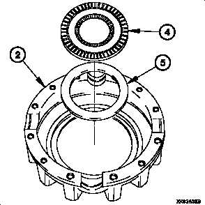
(3) Remove thrust bearing (4) and thrust washer (5) from
bevel gear hub cover (2).
10-12
Change 1