TM 9-2320-365-20-3
11-10. LOAD SENSING VALVE AND CONTROL CABLE REPLACEMENT/ADJUSTMENT
This task covers:
a. Load Sensing Valve Control Cable Removal
b. Load Sensing Valve Control Cable Installation
c. Load Sensing Valve Removal
d. Load Sensing Valve Installation
e. Load Sensing Valve Adjustment
f. Follow-On Maintenance
INITIAL SETUP
Equipment Conditions
Engine shut down (TM 9-2320-365-10).
Air tanks drained (TM 9-2320-365-10).
Tools and Special Tools
Goggles, Industrial (Item 15, Appendix C)
Tool Kit, Genl Mech (Item 44, Appendix C)
Wrench, Torque, 0-175 lb-ft (Item 57, Appendix C)
STE/ICE-R (Item 39, Appendix C)
Materials/Parts
Dispenser, Pressure Sensitive Adhesive Tape (Item
21, Appendix D)
Materials/Parts (Cont)
Antiseize Compound (Item 63, Appendix D)
Tee, Pipe (Item 75.1, Appendix D)
Nut, Self-Locking (2) (Item 148, Appendix G)
Nut, Self-Locking (2) (Item 150, Appendix G)
References
TM 9-4910-571-12 & P
Personnel Required
(2)
WARNING
Wear appropriate eye protection when
working under vehicle due to the
possibility of falling debris. Failure to
comply may result in injury to
personnel.
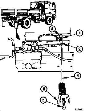
a. Load Sensing Valve Control Cable Removal.
(1) Loosen jam nut (1) on cable clamp (2).
(2) Loosen screw (3) on cable clamp (2).
(3) Remove load sensing valve control cable (4) from cable
clamp (2).
(4) Remove screw (5) and load sensing valve control cable
(4) from bracket (6).
Change 1
11-53


