TM 9-2320-365-20-3
12-5. CENTRAL TIRE INFLATION SYSTEM (CTIS) HOSE ASSEMBLIES, MANIFOLD
VALVE, KNEELING VALVE AND BRACKET REPLACEMENT
This task covers:
a. Removal
b. Installation
c. Follow-On Maintenance
INITIAL SETUP
Equipment Conditions
Engine shut down (TM 9-2320-365-10).
Air tanks drained (TM 9-2320-365-10).
Tools and Special Tools
Goggles, Industrial (Item 15, Appendix C)
Tool Kit, Genl Mech (Item 44, Appendix C)
Fishing Tool, Pneumatic Tire Valve (Item 9,
Appendix C)
Socket, Socket Wrench (Item 68, Appendix B)
Socket, Socket Wrench (Item 36, Appendix C)
Wrench, Torque, 0-175 lb-ft (Item 57, Appendix C)
Wrench Set, Socket (Item 48, Appendix C)
Tools and Special Tools (Cont)
Adapter, Socket Wrench (Item 2, Appendix B)
Materials/Parts
Packing, Preformed (Item 160, Appendix G)
Packing, Preformed (2) (Item 189, Appendix G)
Packing, Preformed (Item 190, Appendix G)
Seal, Nonmetallic (2) (Item 255, Appendix G)
Filter Element, Fluid (Item 16, Appendix G)
Sealing Compound (Item 62, Appendix D)
a. Removal.
WARNING
The sudden release of high pressure air
can cause damage to eyes.
Wear
appropriate eye protection when working
near press-urized air. Failure to comply
may result in injury to personnel.
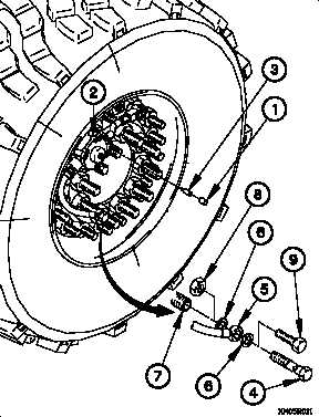
(1) Remove valve cap (1) from CTIS manifold valve (2).
(2) Remove valve core (3) from CTIS manifold valve (2) and
allow time for tire to deflate.
NOTE
Perform step (3) if wheel is mounted on
vehicle.
(3) Remove banjo bolt (4), CTIS hose (5), and two seals (6)
from hollow wheel stud (7). Discard seals.
NOTE
Perform step (4) if wheel was removed from
spare tire retainer.
(4) Remove nut (8), screw (9), and two seals (6) from CTIS
hose (5). Discard seals.
12-8
Change 1


