TM 9-2320-365-20-4
16-8. CAB LEVELING VALVE AND LINKAGE REPLACEMENT/ADJUSTMENT (CONT)
c. Cab Leveling Valve Adjustment.
(1) Lower spare tire (TM 9-2320-365-10).
(2) Start engine (TM 9-2320-365-10).
NOTE
Steps (3) through (5) require the aid of an
assistant.
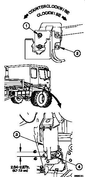
(3) Loosen self-locking nut (1) on cab leveling valve (2).
NOTE
• Rotating cab leveling valve clockwise (to the
right), as seen from right side of vehicle,
decreases cab height. Rotating cab leveling
valve counterclockwise (to the left), as seen
from right side of vehicle, increases cab height.
• Measure air spring to air spring bracket height
on both air springs.
• If air spring to air spring bracket height varies
between sides, but is no more than 0.25 in.
(0.63 cm) outside of upper or lower limit, adjust
cab leveling valve so that average for both sides
is 2.64-2.87 in. (6.7-7.3 cm).
(4) Adjust cab leveling valve (2) until air spring (3) measures
2.64-2.87 in. (6.7-7.3 cm) from bottom edge of air spring
to top surface of air spring bracket (4).
(5) Tighten self-locking nut (1) to 84-108 lb-in. (9-12 N·m).
d. Follow-On Maintenance.
(1) Shut down engine (TM 9-2320-365-10).
(2) Raise spare tire (TM 9-2320-365-10).
End of Task.
16-68
Change 1


