TM 9-2320-365-20-3
14-6. PINTLE HOOK REPLACEMENT (CONT)
b. Installation.
NOTE
All pintle hooks are installed the same way.
M1078 shown.
(1) Position support (1) on rear crossmember (2) with four
screws (3) and self-locking nuts (4).
(2) Tighten four self-locking nuts (4) to 195-239 lb-ft (265-
325 N·m).
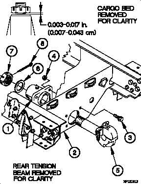
(3) Apply coat of grease to shaft of pintle hook (5).
(4) Install pintle hook (5) in rear crossmember (2) with
washer (6) and nut (7).
CAUTION
Clearance between washer and support must be
0.003-0.017 in. (0.007-0.043 cm). Failure to
comply may result in damage to equipment.
(5) Adjust nut (7) until clearance is 0.003-0.017 in. (0.007-
0.043 cm) with alignment holes lined up between nut and
pintle hook (5).
(6) Install cotter pin (8) in nut (7).
c. Follow-On Maintenance.
Lubricate pintle hook (TM 9-2320-365-20).
End of Task.
14-36
Change 1