TM 939
-2320-365-20-3
Section II. MAINTENANCE PROCEDURES
15-2. RESILIENT MOUNT AND MECHANICAL STOP REPLACEMENT
This task covers:
a. Mechanical Stop Removal
b. Mechanical Stop Installation
c. Resilient Mount Removal
d. Resilient Mount Installation
e. Front Angle Bracket Resilient Mount Removal
f. Front Angle Bracket Resilient Mount Installation
g. Follow-On Maintenance
INITIAL SETUP
Equipment Conditions
Engine shut down (TM 9-2320-365-10).
Cab raised (for front angle bracket resilient mount) (TM
9-2320-365-10).
Tools and Special Tools
Goggles, Industrial (Item 15, Appendix C)
Tool Kit, Genl Mech (Item 44, Appendix C)
Wrench, Torque, 0-175 lb-ft (Item 57, Appendix C)
Tools and Special Tools (Cont)
Crowfoot Attachment, Socket Wrench (Item 5,
Appendix B)
Vise, Machinist (Item 46, Appendix C)
Materials/Parts
Nut, Self-Locking (2) (Item 144, Appendix G)
Washer, Spring (Item 276, Appendix G)
Washer, Spring (Item 280, Appendix G)
WARNING
Wear appropriate eye protection when
working under vehicle due to the
possibility of falling debris. Failure to
comply may result in injury to personnel.
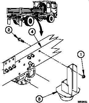
a. Mechanical Stop Removal.
NOTE
Both mechanical stops are removed the
same way. Right rear side shown.
Remove two self-locking nuts (1), bolts (2), and mechanical
stop (3) from frame (4). Discard self-locking nuts.
b. Mechanical Stop Installation.
NOTE
Both mechanical stops are installed the same
way. Right rear side shown.
(1) Position mechanical stop (3) on frame (4) with two
bolts (2) and self-locking nuts (1).
(2) Tighten two self-locking nuts (1) to 118-148 lb-ft
(160-201 N m).
15-2


