CONTINUITY TEST
(1) Remove instrument panel for access (para
7-15).
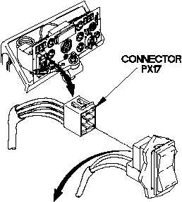
(2) Disconnect connector PX17 from master
power switch connector.
(3) Set multimeter to ohms.
(4) Position master power switch to on.
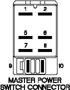
(5) Connect positive (+) probe of multimeter to
terminal 5 on master power switch
connector.
(6) Connect negative (-) probe of multimeter to
terminal 1 on master power switch
connector and note reading on multimeter.
(7) If continuity is not present, replace master
power switch (para 7-18).
(8) Position master power switch to off.
CAUTION
Use care when testing electrical connectors.
Do not damage connector pins or sockets
with multimeter probes. Failure to comply
may result in damage to equipment.
NOTE
Inspect connector pins/sockets for damage,
corrosion, and serviceability. Check that
connector pins are not pushed back and
are capable of making good contact.
Change 1 2-370.5
TM 9-2320-365-20-1